11.1 Electromagnetic induction
Inducing and electromagnetic field
Electromagnetic Induction is a current produced because of voltage production (electromotive force) due to a changing magnetic field.
Electromagnetic Induction was first discovered way back in the 1830s by Michael Faraday.
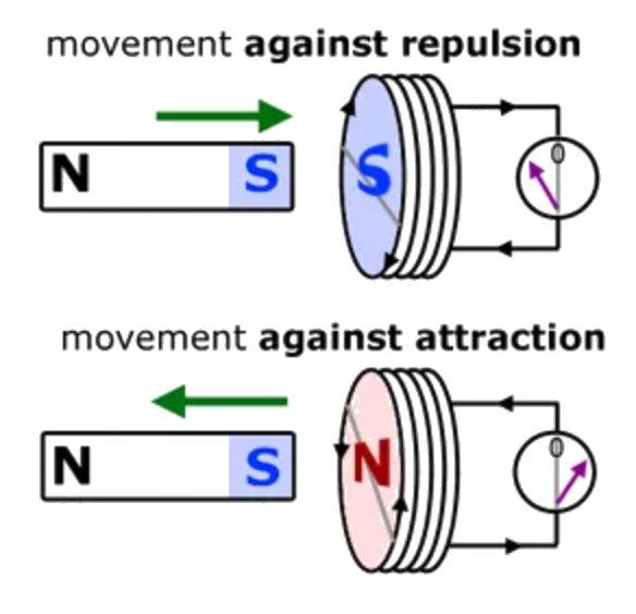
Lenz's law
The direction of the induced current is such as to oppose the change that created the current.
Formulated based on the conservation of energy.

 Video explanation
 Video explanation #2
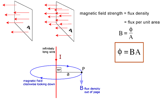
Magnetic flux and flux density
Magnetic flux is a measurement of the total magnetic field which passes through a given area. It is measured in Webers (Wb).
A rate of change of flux of one weber per second induces an emf of one volt across a conductor.
The magnetic field strenght is numerically equivalent to magnetic flux density.
Magnetic flux density is measured in weber meter-2, which is equivalent to one Tesla.
 Video explanation
Magnetic flux linkage
Magnetic flux linkage:
Faraday's law:
The induced emf in a circuit is equal to the rate of change of magnetic flux linkage through the circuit.
Negative sign added to account for Lenz's law.
Faraday's law introductionMichael Faraday's biography (optional)
Changing fields and moving coils
Emf can be induced when:
- a wire of coil moves in an unchanging magnetic field
- the magnetic field can change in strenght
- a coil can change its size and orientation in a constant magnetic field
- a combination of the above
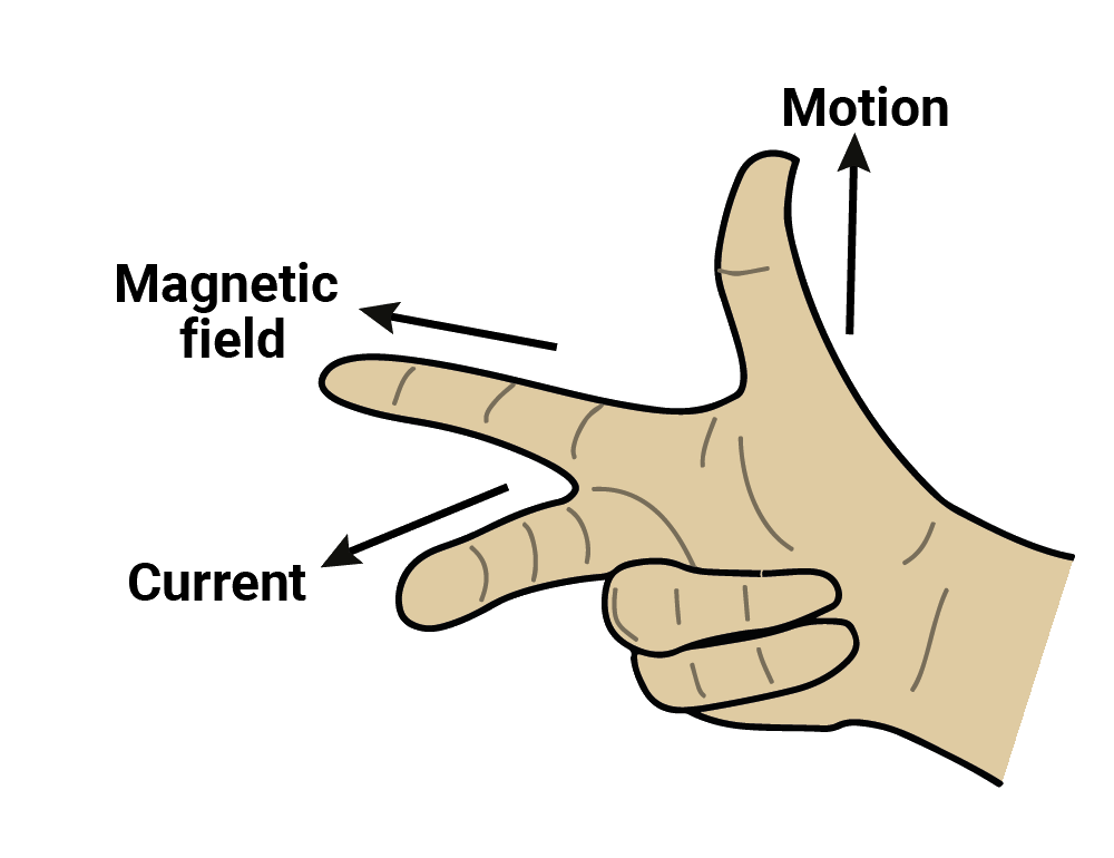
Straight wire moving in a uniform field
The induced emf:
Coil moving
For a coil moving from a position of flux Φ to position of flux 0:
For a coil in a field flipped through 180°:
Magnetic field changes
11.2 Power generation and transmission
Alternating current (AC) generators
AC generator, also known as alternators, is a machine that converts mechanical energy into electrical energy. The generated electrical energy is in the form of an alternating current sinusoidal output waveform. The mechanical energy is usually supplied by steam turbines, gas turbines and combustion engines.
The generated EMF depends on the number of armature coil turns, magnetic field strength, and the speed of the rotating field.
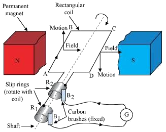
Requirements for an AC generator:
- a rotating coil
- a magnetic field
- movement between the coil and the magnetic field
If the rotation is at constant speed, the induced emf is sinusoidal:
 Video explanation
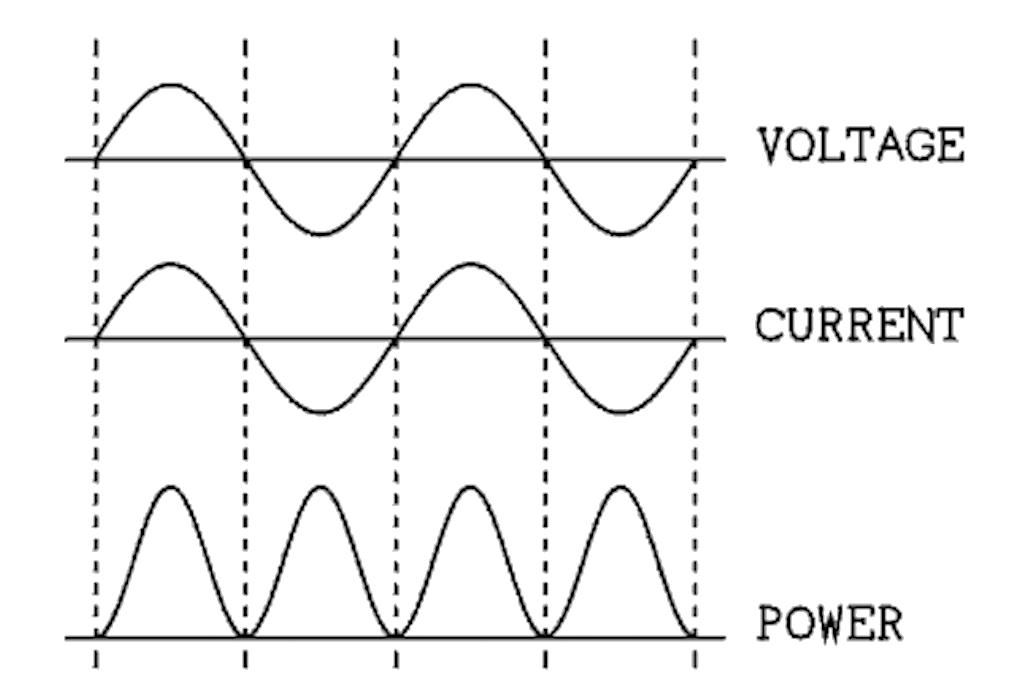
Measuring alternating currents and voltages
The power-time graph is always positive.
The power graph cycles at double the frequency of the current.
Root mean square (RMS) current:
RMS current value can also be defined as the value of the direct current that dissipates the same power in a resistor.
Video explanationTransformers
A Transformer is a static electrical machine which transfers AC electrical power from one circuit to the other circuit at the constant frequency, but the voltage level can be altered that means voltage can be increased or decreased according to the requirement.
A transformer consists of:
- an input (primary) coil
- an output (secondary) coil
- an iron core on which the coils are wound
AC current is supplied to the primary coil. A magnetic field is produced by the current in the primary coil. The magnetic field alternates, as the current is alternating. Induced EMF appears in the secondary coil. Energy is transferred from the primary to the secondary coil.
How does a Transformer work?Transformer rule:
Step-up transformer (output voltage greater than input voltage):
Step-down transformer (output voltage less than input voltage):
Assuming no energy loss:
Efficiency of a transformer:
Ways to improve efficiency:
- Laminating the core (preventing eddy currents)
- Choosing a 'soft' magnetic material
- Choosing low resistance wire (to prevent heating loss)
- Core design that prevents flux leaking out of the core
Transformer problemsHard and soft magnetic materials
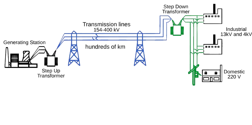
Transformers in action
Power loss in transmission line:
 How Do Substations Work?
Rectifying AC
The process of converting AC into DC is called rectification. A device that carries out this process is known as a rectifier.
What is a Rectifier?Half-wave rectification
A half wave rectifier is defined as a type of rectifier that only allows one half-cycle of an AC voltage waveform to pass, blocking the other half-cycle. Half-wave rectifiers are used to convert AC voltage to DC voltage, and only require a single diode to construct.
 Half wave Rectifier Explained
Full-wave rectification
In a Full Wave Rectifier circuit two diodes are now used, one for each half of the cycle. A multiple winding transformer is used whose secondary winding is split equally into two halves with a common centre tapped connection, (C). This configuration results in each diode conducting in turn when its anode terminal is positive with respect to the transformer centre point C producing an output during both half-cycles, twice that for the half wave rectifier so it is 100% efficient as shown below.
 Full wave Rectifier Explained
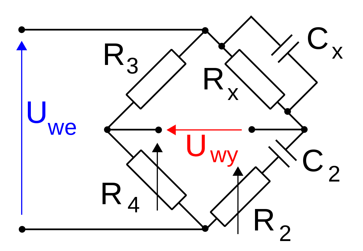
Wheatstone and Wien bridge circuits
The four-diode rectifier arrangement is one of a class of circuits known as bridge circuits
The Wheatstone bridge is used to estimate the resistance of an unknown resistor.

Problems video
The Wien bridge circuit is a modified Wheatstone arrangement that allows to see unknown resistance and unknown capacitance. It uses AC supply.
11.3 Capacitance
Capacitors in theory
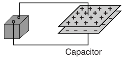
A capacitor is a device that stores electrical energy in an electric field.
It is the arrangement of parallel plates separated by an insulator.
Capacitance is measured in Farads (F), which is coulomb per volt.
Energy stored in a capacitor
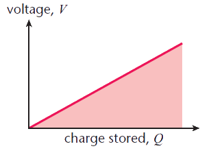
The area under the curve is the energy stored in the capacitor
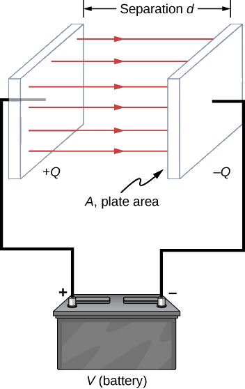
Capacitance of a parallel-plate capacitor
When two parallel plates are connected across a battery, the plates are charged and an electric field is established between them, and this setup is known as the parallel plate capacitor.
Capacitors in practice
Ways to increase capacitance of the plates:
- Make the plate overlap area larger
- Position the plates closer together
- Change the value of permittivity
A dielectric is an insulator that is polarized when in an electric field.
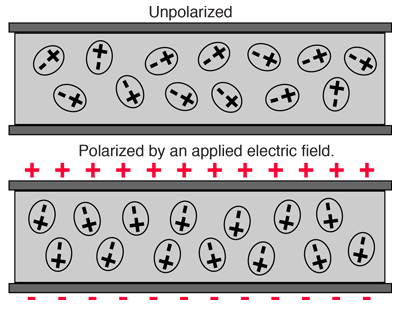
Dielectrics increase the capacitance, as they have increased permittivity than vacuum.
Examples of dielectric materials: paper, mica, Teflon, plastics, ceramics, oxides of some metals.
Relative permittivity chartVideo explanation
Combining capacitors in parallel and series
Another way of changing capacitance values is combining capacitors, in a similar fashion to resistors.
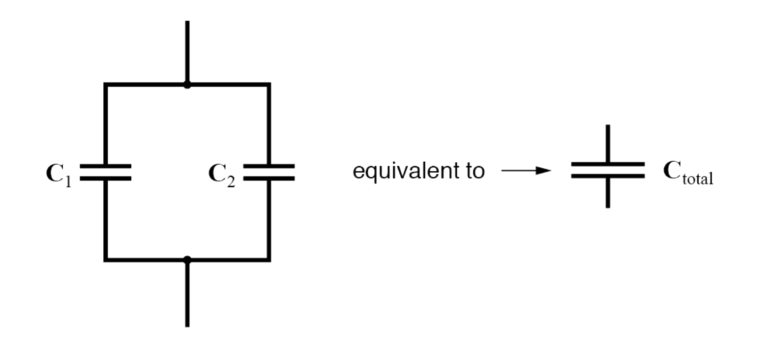
Parallel
When capacitors are connected in parallel, the total capacitance is the sum of the individual capacitors’ capacitances. If two or more capacitors are connected in parallel, the overall effect is that of a single equivalent capacitor having the sum total of the plate areas of the individual capacitors.
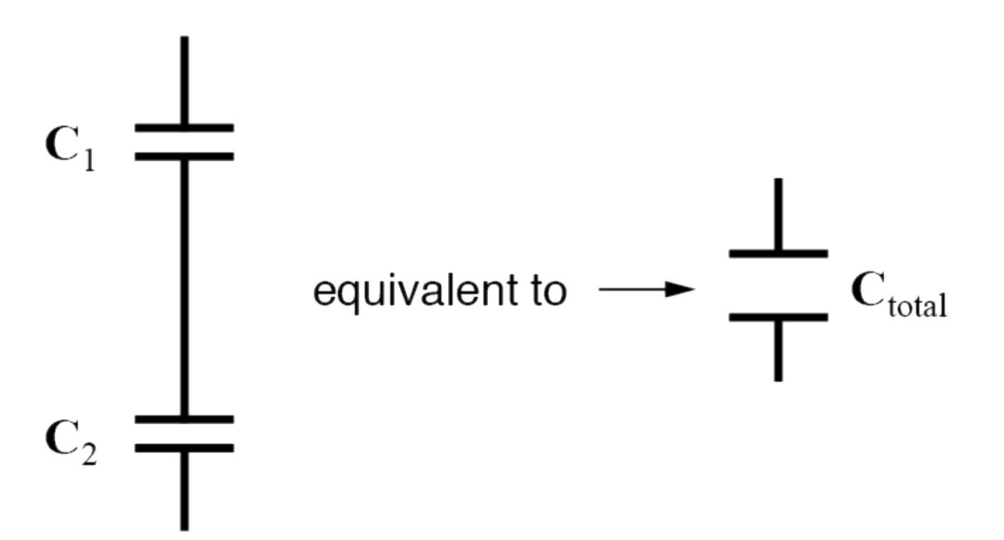
Series
The reciprocal of the total capacitance is equal to the sum of the reciprocals of each capacitance. When capacitors are connected in series, the total capacitance is less than any one of the series capacitors’ individual capacitances.
Discharging and charging a capacitor
Discharging
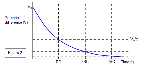
Discharging circuit:
Discharge follows a pattern similar to exponential decay
Charging
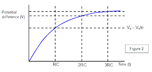 Video explanation
Topic 11 Problems
Number of correct answers: